Utilisation of Tilted R2Sonic 2026 V+ Multibeam Echo Sounder with Unmanned Surface Vehicle in Quay Wall Survey
- saul trewern
- Aug 15, 2024
- 6 min read
Updated: Oct 1, 2024
A case study by: M.Sc. Ezekiel David and M.Sc .ing. Jorge Ibaceta
ABSTRACT
This case study presents an approach to quay wall survey using a tilted R2Sonic 2026 V+ Multibeam Echo Sounder (MBES) deployed on an Unmanned Surface Vehicle (USV). It discusses the system’s extensive features and showcases the effectiveness of the tilted MBES with a USV in assessing the condition of the quay walls and identifying any areas requiring maintenance or repair using part of the Alter Hafen Sud Port in Rostock, Germany as a case study.
INTRODUCTION
Quay walls serve as earth-retaining structures where ships can dock. Typically, they are outfitted with bollards that offer anchorage points for vessels and fenders to cushion the forces exerted by ships. Quay wall surveys are crucial for maintaining the safety and structural efficiency of quay walls in ports and harbours.
USVs are particularly well-suited for surveying in ports and harbors due to several key advantages. Their compact size and agility allow for easy maneuverability in confined and complex environments, making them ideal for navigating tight spaces often found in these areas. USVs, like the MARTAC Systems Mantas T12 used in this survey, can operate with electric propulsion, which is not only cost-effective but also environmentally friendly, reducing both operational costs and emissions. Additionally, the autonomous nature of USVs allows for continuous operations, even in challenging conditions, without the need for human intervention, further enhancing their efficiency and reliability in surveying tasks.
Traditional multibeam beam steering methods often fall short in terms of accuracy, coverage, and outer beam artefacts. Also, having an all-inclusive system where optimal horizontal and vertical structure surveys can be done even in a tight/congested space is difficult. The integration of a tilted R2Sonic 2026 V MBES with a USV offers a promising solution to these challenges and this solution is demonstrated in the Quay wall survey of part of Alter Hafen Sud harbour.
SYSTEM DESCRIPTION
Multibeam
The R2Sonic Sonic 2026 Multibeam Echosounder (MBES) V-Series (Figure 1) is a shaped continuous wave system based on a sixth-generation sonar architecture that networks all modules and embeds the processor, controller, and inertial measurement unit (IMU) in the sonar head receive module to make for a straightforward installation. This all-in-one system minimises lever arm error and angular misalignment between the motion unit and the MBES, resulting in more accurate data collection.

The R2sonic 2026 V has the following technical specifications:
Selectable Frequencies | 170kHz - 450kHz |
|---|---|
Beamwidth | 0.45° x 0.45° at 450kHz |
Number of Soundings per Ping | 1024 |
Near-field Focusing | Yes |
Roll Stabilized Beams | Yes |
Pitch Stabilized Beams | Yes |
User-Selectable Swath Sector in Real-Time | 10° to 160° |
Sounding Depth | 800m+ |
Pulse Length | 15µs -2ms (140µs - 2ms in LF mode) |
Pulse Type | Shaped CW |
Ping Rate | Up to 60Hz |
Bandwidth | Up to 60kHz |
Immersion Depth | 100m |
Bottom Detect Resolution | 3mm |
Min Operating Temperature | -10° C |
Max Operating Temperature | 50° C |
Storage Temperature | -30°C to 55°C |
Mains | 90-260V AC, 45-65Hz, or 10-55V DC |
Power Consumption | 100W avg |
Uplink / Downlink | 10/100/1000Base-T Ethernet |
Sync In, Sync Out | TTL |
Receiver Dim (LWD) | 480 x 109 x 190 (mm) |
Receiver Mass | 12.9kg |
Projector Dim (LWD) | 480 x 109 x 196 (mm) |
Projector Mass | 13.4kg |
The high-resolution characteristics of the R2Sonic 2026 V ensures a very detailed survey for vertical structures.
Unmanned Surface Vehicle
The Autonomous Surveyor (Figure 2) is a 3.6 metre ‘X-Class’ Unmanned Surface Vessel (USV) mobilised with Subsea Europe Service’s integrated Hydroacoustic Survey System (iHSS), representing a paradigm shift in commercial hydrographic survey technology.
The USV is a lightweight solution with unprecedented speed, agility, and reliability. It offers complete deployment flexibility and overcomes the manoeuvring and speed limitations of manned survey vessels and standard USVs. The vessel offers new levels of operator control flexibility, including full and semi-autonomous, and human-in-the-loop operations.

The USV has the following characteristics:
Length | 3.6m |
Width | 0.90m |
Height | 0.36m |
Draft | 0.18m (without payload) |
Vessel fully equipped | 210kg |
Maximum payload weight | 64kg |
Top Speed | up to 30 Knots (depending on payload) |
Survey Speed | 2-12 Knots |
Propulsion | Twin Screw Electric |
Ocean capability | SS4 (1.25-2.5m) |
Survivability | SS5 (2.5-4.0m) |
Survey capability | SS2 (0.1-0.5m) |
Transit Speed | up to 12 knots (depending on payload) |
Survey Speed | 2-12 knots |
With the characteristics of the USV, the vehicle is capable of navigating into tight and smaller spaces and under structures in ports and harbours.
METHODOLOGY
Survey Location
To demonstrate the effectiveness of the tilted R2Sonic 2026 V MBES with a USV, a survey of part of the Alter Hafen Süd port, Rostock was conducted. The objective of the survey was to assess the effectiveness of the tilted system in assessing vertical structures. For this, the USV was deployed and and tested at part of the harbour where access was not hindered.

Setup
The R2Sonic 2026 V MBES was mounted on the USV using a tilted flange (figure 3). The position and motion system (the SBG Pulsar 40) whose motion unit is imbedded in the MBES receiver and the dual antennas fixed approximately 2.5m apart on the USV were utilised for high precision positioning, motion, and heading of the setup. For the survey, a tilt angle of 25 degree was set considering the depth of the tilted flange and the space underneath the USV.

The Dimension control of the tilted setup was done, and a vessel configuration was created. Beamworx Navaq was used for the data acquisition, a sound velocity profile in the area was taken, a patch test was conducted, and then the survey data of the quay wall was acquired for processing and analysis. A remote workstation (figure 4) was setup and close to the pier and it served as our observation point for the USV while in operation according to the rules of utilising USVs in open waters.
RESULTS
Data processing and presentation
After data capture, the BeamworX autoclean was used to process and analyze the data.
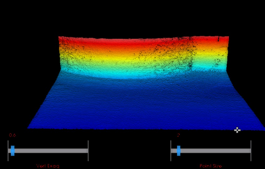
A survey grid of 0.015m (15cm) was used to create a detailed 3D model of the quay wall and its environs.


A 3D model of the whole area showing the wall, pillars and other objects on the seabed was created.


The multibeam depth was 0.60cm below the water surface, and with the 25° tilt, the quay wall up to 0.9m below the water surface was reached.


OUTCOME & BENEFITS
The survey successfully demonstrated the benefits of using a tilted R2Sonic 2026 V MBES with a USV for quay wall surveys. The high-resolution data collected by the MBES provided a detailed and accurate representation of the quay wall, useful in the identification of potential issues and deformation promptly. The use of the USV ensured the safety of the survey team and allowed for efficient data collection in tight and hard-to-reach areas.
The survey also highlighted the advantages of the tilted system over traditional beam steering methods for vertical structures. They include:
Optimized Angle of Incidence: A tilted multibeam system aligns the beams more perpendicularly to the vertical surface, enhancing the quality and accuracy of the returned signal. This reduces incidence angle-related distortions and increases the fidelity of the data
Enhanced Surface Detail: With a tilted multibeam, the sonar beams are directed straight at the vertical wall, capturing more detailed and accurate representations of the surface features
Reduced Complexity: The inherent design of a tilted multibeam system simplifies surveying vertical structures, reducing the need for complex beam steering algorithms and operator interventions
Improved Coverage: Depending on the tilted angle, the part of the quay wall close to the water line can be surveyed
Minimized Noise and Artefacts: The system minimizes the noise and artefacts that result from poor incidence angles, improving the overall quality of the survey data.
LIMITATION
The survey lines can only be done in one direction (to have the tilted face on the vertical wall) therefore longer turn times are experienced for overlapping surveys.
Flange was not long as such, higher tilt angle was not possible with the available space underneath the USV. With more tilt, even areas higher than the MBES depth can be reached
CONCLUSION
R2Sonic 2026v+ is a new class MBES with embedded IMU, minimising lever arm error and angular misalignment between the motion unit and the MBES
The MBES is utilised in a tilted mode, and this gives a higher coverage for vertical wall survey and utilises the beams optimally
The tilted MBES is deployed on an Unmanned vehicle so it can go into tight and smaller spaces and under structures in ports and harbours
The R2Sonic 2026 V+ MBES’s high-resolution characteristics ensure a very detailed quay wall survey
There are better benefits in utilising the tilted system compared to steering the beams. for example:
Optimized Angle of Incidence: A tilted multibeam system aligns the beams more perpendicularly to the vertical surface, enhancing the quality and accuracy of the returned signal. This reduces the incidence angle-related distortions and increases the fidelity of the data.
Enhanced Surface Detail: With a tilted multibeam, the sonar beams are directed straight at the vertical wall, capturing more detailed and accurate representations of the surface features.
Reduced Complexity: The inherent design of a tilted multibeam system is simpler for surveying vertical structures, reducing the need for complex beam steering algorithms and operator interventions.
Depending on the tilted angle, the part of the quay wall close to the water line can be surveyed
Minimizes the noise and artefacts that can result from poor incidence angles, improving the overall quality of the survey data.
Contact us for help in addressing your port & harbour, nearshore or offshore marine survey challenges.